Energy Update


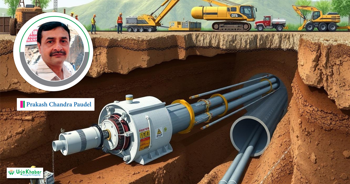
Microtunneling: Applications in Urban Development and Project Guidelines
-
 प्रकाश चन्द्र पौडेल
- 20 August, 2025
1 Introduction and Applications
Microtunneling is the most practical technology for urban development in developing countries like Nepal. It is a rapidly growing sector of the construction and civil engineering industry. It is a trenchless underground construction method employed to accurately install pipelines under existing utilities, highways, railroads, levees, waterways, unstable ground conditions, and contaminated soils. The major applications for pipe jacking and microtunneling include new sewerage and drainage construction, sewer replacement and lining, gas and water mains, oil pipelines, electricity, telecommunications cable installation, and culverts. Special applications include the installation of rectangular or circular sections for pedestrian subways, road underpasses and bridge abutments.

The pipe jacking method can deliver environmental benefits in excess of 75 percent by reducing carbon emissions compared to disruptive open-cut construction, which requires considerably greater amounts of excavation and substantial backfill material. The pipe jacking method generally requires less overbreak than segmental tunnels and provides ground support and reduces potential ground movement. In many cases the use of pipe jacking techniques instead of open trenching contributes positively towards workplace safety, the interface with the general public and the environment.
2. Site Selection and Design Criteria
The site selection is based on the provision of safe clearance to the project structures from critical and sensitive building foundations as well as existing utility services. The most practical and commonly used equipment for detecting underground utilities is the Ground Penetrating Radar (GPR). The GPR detects underground facilities, such as drainage & sewage pipelines, electric cables, optical cables, telecom lines and other metallic objects.
In addition, other essential data for the detail design are the stability and friction characteristics of the soil/ rock to be tunneled through the self-weight & strength of the jacking pipes, the diameter of the pipe, the type of excavation method, and the available jacking reaction. The major constraint will be the nature of the ground and groundwater characteristics.
Other geotechnical properties for the design include shear strength, allowable bearing capacity, SPT (N) value, and coefficient of permeability of the soil.
Investigations by surface geological survey, borehole drilling, and electrical resistivity tests can confirm the nature of soil and its permeability condition. The static cone penetrometer test (CPT) can be carried out in soft ground using a 100kN Lightweight Cone Penetrometer to estimate soil type, coefficient of permeability, SPT, shear strength, Young’s modulus, and shear modulus of the soil/rock layers.
Seismic shear wave velocity in the soil/rock layers may also be required.
3. Tunnel Boring Equipment Selection Process
In view of the geological and hydrological conditions of the special construction area, selection of a pipe jacking machine has become one of the key measures for construction risk control of the project.
Earth pressure balance machine (EPBM) is a fullface tunnel boring machine in which the excavated material is transported from the face by a balanced screw auger or screw conveyor. The face is supported by excavated material held under pressure behind the cutter head in front of the forward bulkhead. Pressure is controlled by the rate of outgoing excavated material through the balanced screw auger or valves on the screw conveyor.
EPBMs work best in cohesive soils. Where sand and gravels are encountered in a mixed face, these may be conditioned by injecting additives such as bentonite, water or polymers into the plenum and/or the screw to plasticize them.
The Slurry Balance Machine uses pressurized slurry to balance the groundwater and soil pressure at the face that helps in stabilizing the excavated surfaces and minimizing the ground settlement. It has a closed chamber to maintain the slurry pressure on the face. The slurry is pumped out and recycled from the surface. It is also equipped with a stone crusher for crushing cobbles. Various cutting heads are available to suit a broad range of ground conditions and may incorporate internal crushers to deal with cobbles and small boulders. This machine is suitable for water-bearing silts and sands with fine gravels.
The slurry balanced machine is comparatively simpler, less risky and a quicker process than the EPB machine.
4. Microtunneling Process
Microtunneling systems are remotely controlled and comprise several subsystems that function together. They are managed by an operator who monitors and controls pipe jacking operations from a control cabin inside a container on the surface beside the jacking shaft. MTBMs are accurately controlled by exerting continued support at the tunnel face by balancing thrust pressure and slurry with groundwater and earth pressures. The operator also monitors the position of the machine and the temperature of the driven motors from the control cabin.
The front part of the jacking equipment, together with its ancillaries, is set in the shaft along a cradle connected to the thrust wall. To drive the jacking equipment, jacking force is applied through the jacking frame cylinders installed on the thrust wall.
After driving the jacking equipment, a little into the ground and setting up the tunnel axis, the jacking pipe is installed at the backside of the equipment with a rubber gasket to continue the driving operation. In this way, jacking pipes are pushed into the tunnel one by one, simultaneously with the excavation.
5. Microtunneling Guidance System
Steering of the equipment is controlled by hydraulic cylinders that are connected to the cutter head. A laser guidance system is set in the computer for monitoring the alignment and position of the jacking equipment. With this guidance, the operator can steer the cutting head. The laser guidance system is set with the calculated value to guide the excavation. The location of the laser machine is set according to the tunnel alignment position. The operator can check the deviation status of the tunnel drive and adjust the direction of the cutter head, driving the boring equipment slowly and carefully from the control cabin while controlling the deviation within the tolerance limit. The tolerance limit for tunnel jacking is ±50 mm on the horizontal line and ±35 mm on the vertical line.
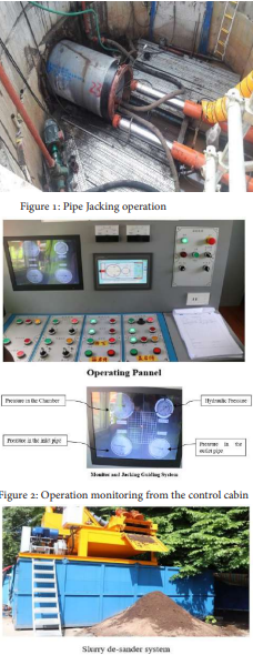
Figure 3 : The slurry seperation tank
1. Jacking Load
Loads required to jack the pipeline forward are mainly a function of frictional forces built up around the pipeline. These forces depend on the type of ground, its arching characteristics, friction angle, the depth of overburden, the depth of the groundwater & any surcharge load, the length and diameter of the pipe being jacked and the time taken for the operation.
As much as hundreds of tons of force may be required to push the machine and liner forward. The jacking frame containing hydraulic rams produces these forces. The jacking shaft must be strong enough to support the forces it generates.
The friction of the ground around the pipe increases in proportion to the tunnel length. Two practices can minimize this friction. First, over-cutting is used to provide a gap between the tunnel and the outer edge of the liner. The gap is between 13 to 38 mm. A lubricant, often bentonite slurry, is injected into this gap. The pressure of the lubricant prevents the gap from collapsing.
2. Intermediate Jacking Stations
When the total jacking load exceeds the allowable jacking load of the pipe, the intermediate jacking station is to be installed. Inter jacking stations are not only used to increase the jacking lengths achievable but also to reduce the loads that are transmitted to the shaft structure.
3. Jacking Pipes
Jacking pipes are manufactured with a variety of materials that include concrete, clay, GRP and steel. Standard pipe diameters generally range from 0.5 to 4 m in diameter or greater if required. Jacking lengths can be in excess of 1 km depending on the pipe diameters, ground conditions and excavation methods.
4. Tunnel Stability Analysis
The tunnel stability calculation is based on the Mohr-Coulomb failure criteria and Peck’s Ground Settlement Theory (1969). Maximum shear stress is considered as the vertical pressure that should be less than the shear strength on stability condition. The vertical pressure is determined by the ground cover and unit weight of the material.
The Principle of Peck’s Ground Settlement Theory is that the volume of surface settlement is assumed to be equal to the volume of the lost ground. In normal circumstances, the volume of the lost ground shall be 1.5 to 3%. Greater ground loss can occur, especially if boulders are caught in a rotating cutter, a run or flow of sand or silt occurs, squeezing of clays or silts, unequal excavation of a soft material in a mixed-face situation.
Methods that reduce the lost ground include full and proper face control at all times, especially while shoving the shield, limiting the length-to-diameter ratio for the shield, rapid installation of ground support, and pea gravelling or contact grouting of ground support. In critical situations, consolidation grouting of the ground before tunneling or from the tunnel face during excavation shall be required.
5. Risk Assessment and Monitoring Plan
Basic principles of the risk assessment and monitoring plan during the construction of tunnels and shafts are as follows:
i. High water inflow may occur in the tunnel.
ii. Contamination of groundwater may occur.
iii. Gradual damage to utility service lines may occur due to non-uniform settlement of ground.
iv. Occurrence of overbreak in the tunnel and total ground settlement should not exceed 2 cm.
v. Ground subsidence may cause damage of public roads, railway lines or the nearby building structures.
vi. Tilting of high, rigid buildings and cracking of panels & brick walls may occur if the total settlement exceeds 3.5 cm.
vii. Ground subsidence may cause noise and traffic congestion on the road.
6. Shaft Structures
Locations for the shafts are designed based on existing manholes, easy connection to the mainline, their impact on the surrounding buildings or facilities, and crossings of utility lines through the tunnel alignment. Construction methods include segmental lining, pre-cast or cast-in-situ concrete, sheet piling, ground anchorage, etc. The shape of the shafts may be circular, rectangular or polygonal based on the working platform, geological condition of the ground, and stability condition of the surrounding buildings. The size of the shaft shall be determined by calculating the length and diameter of the jacking machine, the length of jacking cylinder, the space for joining the jacking pipes, and the thickness of the thrust wall.
The Microtunnel Boring Machines (MTBMs) install pipelines from the jacking shaft to the receiving shaft. A concrete reaction wall is constructed at the rear of the jacking shaft to disperse the jacking loads onto the jacking pipe. The jacking frame tonnage and jacking pipe loads are properly calculated during the design.
Ground treatment or groundwater management can be performed by construction of wells, grouting, or ground freezing.
7. Grouting
For nearly all soft ground tunnels (the one exception being those supported by shotcrete), such contact can be stabilized only by expansion of the support system by grouting in contact between the excavated tunnel surface and the support system. Based on the purpose of execution, grouting can be categorized into the following types:
1. Permeation Grouting is the direct pressure injection of a chemical fluid grout into the ground to fill the spaces between and bind together soil particles without causing excessive movement or fracturing of the soil formation. It is performed prior to the commencement of tunneling operations to provide a more consistent and stable soil matrix.
2. Contact Grouting: The annulus between the pipe and the ground shall be grouted after pipe jacking is completed. Grouting shall be performed over the entire 360˚ circumference of the tunnel. Grout shall consist of Portland cement & water and sometimes may contain sand, bentonite or fly ash.
3. Consolidation Grouting or Jet Grouting, is conducted around the outer periphery of the shaft to prevent possible failure of side walls and sand boiling from the invert during excavation. Grouting pressure for consolidation grouting ranges from 3 to 7 bar, whereas Jet Grouting shall require a high pressure which can be up to 25 MPa. Necessary equipment for grouting includes drilling equipment, grouting equipment and a generator.
The author is a sr. geologist and he is associated with Seti Khola Hydropower Company Ltd., located in Kaski.
Conversation

More News


- Nepal's First Energy Based News Portal
-
Energy Information Center Pvt. Ltd.
Hemant Marg-11, Babar Mahal, Kathmandu
- Info. Dept. Reg. No. : 254/073/74
- Telephone : +977-1-5321303
- Email : [email protected]